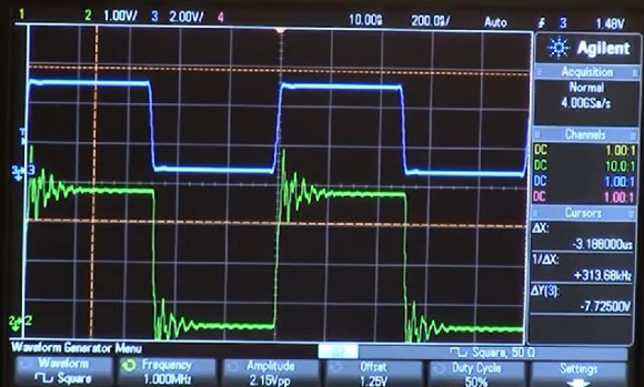
In high speed digital circuits, fast doesn’t necessarily mean “high clock rate”. [Jack Ganssle] does an excellent job at explaining how the transition time of signals in high speed digital circuits is just as important as the speed of the signal itself. When the transition time is large, around 20 nanoseconds, everything is fine. But when you cut it down to just a few nanoseconds, things change. Often you will get a ringing effect caused by impedance mismatch.
As the signal travels down the trace from the driver and hits the receiver, some of the signal will get reflected back toward the driver if the impedance, which is just resistance with a frequency component, does not exactly match. The reflected signal then heads back to the driver where the impedance mismatch will cause another reflection. It goes back and forth, creating the ‘ringing’ you see on the scope.
[Jack Ganssle] goes on to explain how a simple resistor network can help to match the impedance and how these should be used in circuits with fast transition times, especially where you will be taking readings with a scope. As the scope probe itself can introduce impedance and cause the ringing.
In case you didn’t pick up on it, [Jack Ganssle] also happens to be one of the judges for The Hackaday Prize.
Filed under: misc hacks
